15. REAR WHEEL/AXLE/SUSPENSION
DRIVING MECHANISM MXU 250R/300R
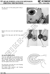
Remove he oil cap.
(1)
Rotate ring gear several turns in each
direction.
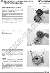
Check the gear tooth contact pattern through
the oil filler hole.
This will provide a contact pattern on the Incorrect:
coated teeth of the gear. Contact at tooth top
Compare the coated teeth to the examples
shown in (1), (2) and (3).
(2)
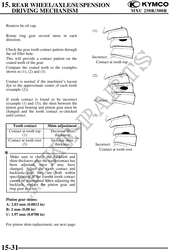
Contact is normal if the machinist's layout
dye to the approximate center of each tooth
(example (2)).
If tooth contact is found to be incorrect Correct
(example (1) and (3)), the shim between the
pinion gear bearing and pinion gear must be
changed and the tooth contact re-checked
until correct. (3)
Tooth contact Shim adjustment
Contact at tooth top Decrease shim
(1) thickness
Contact at tooth root Increase shim
(3) thickness Incorrect:
Contact at tooth root
Make sure to check the backlash and
shim thickness after the tooth contact has
been adjusted, since it may have
changed. Adjust the tooth contact and
backlash until they are both within
specification. If the correct tooth contact
cannot be maintained when adjusting the
backlash, replace the pinion gear and
ring gear as a set.
Pinion gear shims:
A: 2.03 mm (0.0812 in)
B: 2 mm (0.08 in)
C: 1.97 mm (0.0788 in)
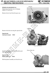
For pinion shim replacement, see next page.
15-31