19. SWITCHES/HORN/FUELUNIT/THERMOSTATICSWITCH
/TEMPERATUREGAUGE/INSTRUMENTS/LIGHTS GRAND DINK 125/150
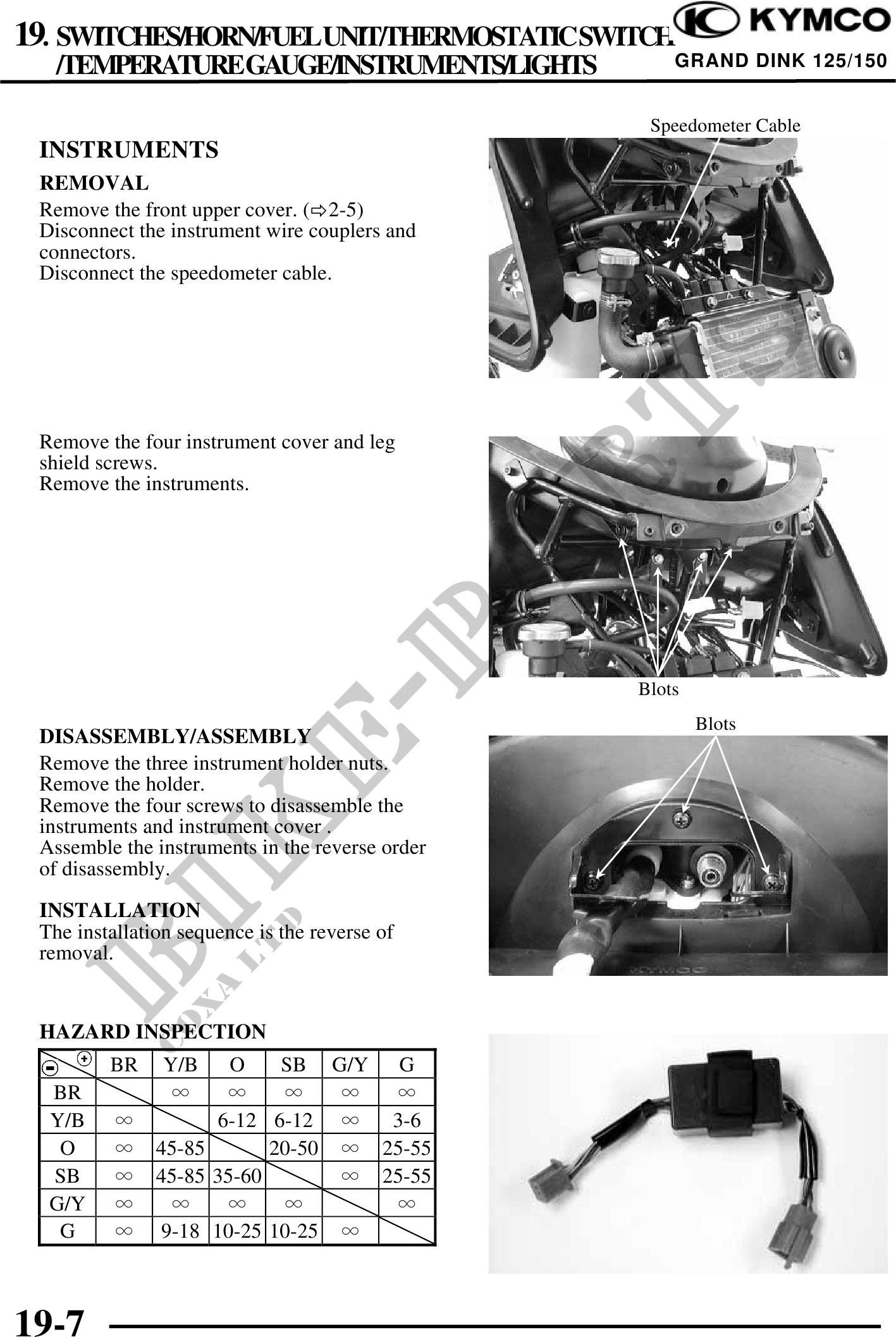
Speedometer Cable
INSTRUMENTS
REMOVAL
Remove the front upper cover. ( 2-5)
Disconnect the instrument wire couplers and
connectors.
Disconnect the speedometer cable.
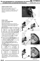
Remove the four instrument cover and leg
shield screws.
Remove the instruments.
Blots
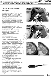
Blots
DISASSEMBLY/ASSEMBLY
Remove the three instrument holder nuts.
Remove the holder.
Remove the four screws to disassemble the
instruments and instrument cover .
Assemble the instruments in the reverse order
of disassembly.
INSTALLATION
The installation sequence is the reverse of
removal.
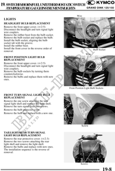
HAZARD INSPECTION
BR Y/B O SB G/Y G
BR
Y/B 6-12 6-12 3-6
O 45-85 20-50 25-55
SB 45-85 35-60 25-55
G/Y
G 9-18 10-25 10-25
19-7