Il mio carrello

| Descrizione | Codice | Qtà |
|---|
| Descrizione | Codice | Qtà |
|---|
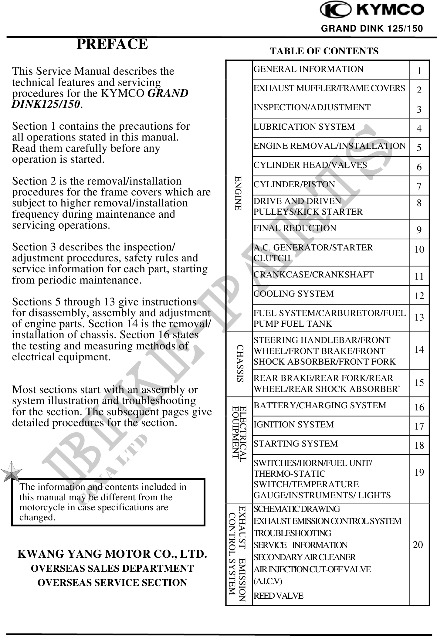
                                                                                         GRAND DINK 125/150
              PREFACE                                               TABLE OF CONTENTS

This Service Manual describes the                                GENERAL INFORMATION               1
technical features and servicing                                 EXHAUST MUFFLER/FRAME COVERS
procedures for the KYMCO GRAND                                                                     2
DINK125/150.                                                     INSPECTION/ADJUSTMENT             3
Section 1 contains the precautions for                           LUBRICATION SYSTEM                4
all operations stated in this manual.
Read them carefully before any                                   ENGINE REMOVAL/INSTALLATION       5
operation is started.                                            CYLINDER HEAD/VALVES              6


                                                   ENGINE
Section 2 is the removal/installation                            CYLINDER/PISTON                   7
procedures for the frame covers which are
subject to higher removal/installation                           DRIVE AND DRIVEN                  8
frequency during maintenance and                                 PULLEYS/KICK STARTER
servicing operations.                                            FINAL REDUCTION                   9
Section 3 describes the inspection/                              A.C. GENERATOR/STARTER            10
adjustment procedures, safety rules and                          CLUTCH
service information for each part, starting                      CRANKCASE/CRANKSHAFT
from periodic maintenance.                                                                         11
                                                                 COOLING SYSTEM                    12
Sections 5 through 13 give instructions
for disassembly, assembly and adjustment                         FUEL SYSTEM/CARBURETOR/FUEL
                                                                                             13
of engine parts. Section 14 is the removal/                      PUMP FUEL TANK
installation of chassis. Section 16 states                       STEERING HANDLEBAR/FRONT
the testing and measuring methods of
                                                    CHASSIS


                                                                 WHEEL/FRONT BRAKE/FRONT           14
electrical equipment.                                            SHOCK ABSORBER/FRONT FORK
                                                                 REAR BRAKE/REAR FORK/REAR
                                                                                                   15
Most sections start with an assembly or                          WHEEL/REAR SHOCK ABSORBER`
system illustration and troubleshooting                          BATTERY/CHARGING SYSTEM           16
                                                EQUIPMENT
                                                ELECTRICAL


for the section. The subsequent pages give
detailed procedures for the section.                             IGNITION SYSTEM                   17
                                                                 STARTING SYSTEM                   18
                                                                 SWITCHES/HORN/FUEL UNIT/
                                                                 THERMO-STATIC                     19
 The information and contents included in                        SWITCH/TEMPERATURE
 this manual may be different from the                           GAUGE/INSTRUMENTS/ LIGHTS
 motorcycle in case specifications are                           SCHEMATIC DRAWING
                                              EXHAUST EMISSION
                                               CONTROL SYSTEM


 changed.                                                        EXHAUST EMISSION CONTROL SYSTEM
                                                                 TROUBLESHOOTING
                                                                 SERVICE INFORMATION               20
 KWANG YANG MOTOR CO., LTD.                                      SECONDARY AIR CLEANER
    OVERSEAS SALES DEPARTMENT                                    AIR INJECTION CUT-OFF VALVE
     OVERSEAS SERVICE SECTION                                    (A.I.C.V)
                                                                 REED VALVE